A brief introduction into High Availabilty
Keeping data identical at two locations is becoming increasingly important in a highly available IT world. A couple of years back in time it used to be an expensive enterprise level luxury. But recently that demand can be found in SMB environments too. The method is called mirroring which can be implemented in two ways.
- Asynchronous – Data is being synchronized in defined intervals. In between there is a difference (delta) between source and target.
- Synchronous – Data transfer is transaction consistent. I.e. the data is identical on both sides at all times. A write operation is only considered complete when source and target site have confirmed the write.
A prerequisite for high availability is mirroring of data (synchronous or asynchronous). If the data is available at two locations (data centers), a further design question arises: Should the storage target act as a fallback copy in case of emergency (Active-Passive), or should the data be actively used in both locations (Active-Active)?
- Active-Passive – Only the active side works and data is transferred to the passive side (synchronous or asynchronous). In case of a failiure, the system switches automatically or manually and the previously passive side becomes active. It remains so until a failback is triggered. This method guarantees full performance even in the event of a total site failure. Resources must be equal on both sides. The disadvantage is that only a maximum of 50% of the total resources may be used.
- Active-Active – Resources of both sides can be used in parallel and the hardware is utilized more efficiently. However, this means that in the event of a failure, half of the resources are lost and full performance cannot be guaranteed. Active-Active designs require a synchronous mirror, as both sides have to work with identical data.
Active-Active clusters do exist in many different forms. There’s classic SAN storage with integrated mirroring, or software defined storage (sds) where the mirroring is not in hardware but in the software layer. One example is DataCore SANsymphony. VMware vSAN Stretched Cluster plays a special role and will not be covered in this post.
In the following section I will discuss a special pitfall of LUN based active-active constructs, which is often neglected, but can lead to data loss in case of an error. VMware vSAN is not affected because its stretched cluster is based on a different design which prevents the following issue.
Let’s look at an active-active cluster with a synchronous mirror. Whether this is implemented in hardware at controller level or in software isn’t important for now.
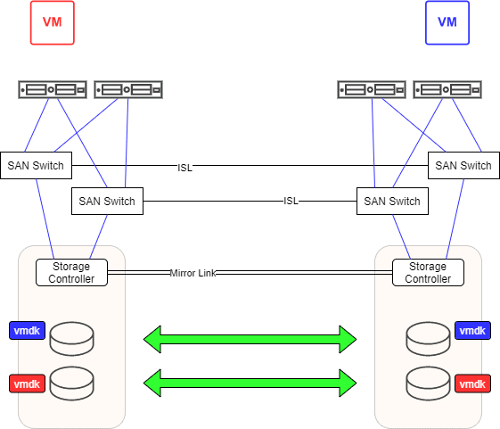
The situation
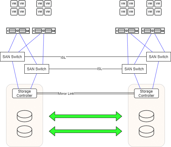
In the picture above we see a typical active-active cluster. A redundant mirror path is used to keep mirrored LUNs in sync. There are two independent fibrechannel fabrics with one SAN switch on each side. Both switches of a fabric are connected via an Inter-Switch-Link ISL. Each storage controller has redundant connections to both fabrics. On both sides there are ESXi hosts which also have redundant paths to both fabrics. Each host has 4 paths to a LUN. Two (preferred) local paths and two remote paths. In case of any failure a transparent failover will take place. If, for example, one of the two storage devices fails, all workloads continue to run seamlessly on the remaining storage. After the damage is repaired, the changes are synchronized via the mirror path. So far, so good.
Each VM can be migrated by vMotion from data center 1 (DC1) to data center 2 (DC2) and back again if required. Any VM can be assigned to LUNs automatically (storage-vMotion) or manually. So we have two selection criteria: compute (ESXi) and storage (LUN). This creates high flexibility. Automatisms built into vSphere ensure optimal load distribution.
To clarify the scenario, let us consider only 2 VMs (red and blue) that reside on the same mirrored LUN (vmdk red and vmdk blue). VM red runs in DC1 and VM blue in DC2.
Where’s the problem?
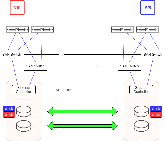
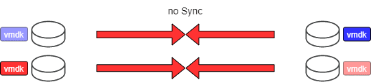
This design gets interesting when both data centers become isolated from each other. Imagine an excavator that accidentally cuts the optical fibers between the two data centers.
What will happen to our VMs? VM red loses half of its paths to remote storage in DC2. However, the local LUN in DC1 remains accessible. VM red will continue to run. For VM blue the situation looks similar. It can access the LUN in DC2 and loses all paths to the remote LUN in DC1. VM blue will also continue to run. We now have an active VMDK file for VM red in DC1 and an orphaned copy in DC2 (light red). For VM blue it is just the other way round. Without realizing it, we are dealing with two living zombies. Like Schrödinger’s cat, the VM is active or lost. But you’ll only notice when the connections between both data centers is restored.

We now have a situation where the image and mirror image of the LUN have evolved in different directions, which cannot be synchronized again. We call that a split-brain scenario. The administrator now has to choose one side to survive and sacrifice the other. The chosen site will be entirely copied to the destination site, overwriting all data there. If he decides to keep DC1, VM red remains in the most current state, but VM blue will fall back to a state right before the connection was disconnected (light blue). The current version of VM blue will be lost. If he chooses DC2, VM blue remains current, but VM red falls back to the old version (light red). Caught between a rock and a hard place.
Prevention
The scenario described above could have been avoided. It requires only a little planning and control. The effort is manageable and all necessary resources are already included in vSphere.
If we assign mirrored LUNs to one or the other data center and also assign half of our VMs to one or the other data center the situation could have been untangled without pain.
Let’s assume that VM red belongs to VM group DC1 and VM blue to VM group DC2. We can create a soft DRS rule for this. Under normal conditions VM red should run on hosts in DC1 and VM blue on hosts in DC2. If we now make sure that all VMs in group DC1 reside on a datastore (or datastore cluster) for DC1 and do the same with the VMs in group DC2, we can achieve a clean separation.
All VMs in DC1 reside on designated DC1 data stores. The same applies to VMs in DC2. If the excavator strikes, VMs on both sides continue to run as before. And also the mirrored LUNs will diverge completely. In contrast to the first scenario, however, we now have the LUNs sorted by side. On some LUNs there are only VMs from DC1, and others LUNs will only hold VMs from DC2.
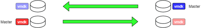
Now the decision which side to declare active will be easy. The decision can be taken on LUN level. So you can declare one LUN master in DC1, overwriting the corresponding mirror in DC2. For the next LUN you can do it the other way round. So you can make sure only to overwrite old data and keep the most recent Version of your VMs. In our example below the most recent vmdk (blue and red) will overwrite the old ones (light blue and light red).
What happens during normal hardware failure?
Doesn’t this intervention lead to less flexibility, or to a reduction in high availability? Clearly not. Let’s take a look at the various failure scenarios.
ESXi host failure
If one of the two hosts in DC1 fails, the remaining host will try to take over the VM workloads. If the resources of the host aren’t sufficient to take the load, our soft DRS rule will ensure that VMs can also be temporarily run on hosts in DC2. After the problem is resolved, DRS will migrate the VMs back.
Storage failure
In case of a storage failure, all VMs will perform a transparent path failover. This won’t cause any problems, because every LUN is accessible on every storage. After eliminating the problem, all VMs will access their local LUN on their local storage unit via their preferred (local) paths.
Proper planning
Of course, you have to spend a few thoughts in advance. The resource requirements (RAM, CPU) should be distributed more or less equally between the two data centers. Also the allocation of storage, or more precisely the accesses to it (i/o) should be even on average. VMs with active data exchange should be grouped on the same data center. This keeps the paths of the data packets short. If possible, several LUNs should be grouped into datastore clusters for each side. This will give storage-DRS flexibility for load balancing.
The total cluster load should be sized in such a way that even in case of failure of an entire data center, there’ll be still enough resources to run all VMs. This can be achieved with HA admission control.
If it turns out that VMs should change sides, it is important that the data store is also changed accordingly. If you don’t show discipline here, you’ll end up in a situation I’ve outlined in the beginning.
Tools
There are a number of useful tools to help you make the right sizing. VMware vRealize Operations can provide deep insight into the resource requirements of your VMs and might help you to plan resource allocation or redistribution, if necessary. VMware vRealize Network Insight can answer questions about inter-VM communication.
With limited budget you can utilize free software like RVTools. It’ll give you a good insight to all VMs, datastores, memory and CPU-requirement. Although it won’t provide any information about i/o you can use esxtop together with Perfmon to enrich the data gained with RVTools.