VMware vSAN was developed about 10 years ago. The year was 2012, when magnetic disks were predominantly used for data storage and flash media was practically worth its weight in gold. It was during this time that the idea behind vSAN was born. Hybrid data storage with spinning disks for bulk data and flash media as cache. Flash devices at this time used the same interfaces and protocols as magnetic disks. As a result, they were not able to unfold their full potential. There was always the bottleneck of the interface.
Today – a more than 10 years later – we have more advanced flash storage with high data density and powerful protocols such as NVMe. The price per TB for flash is now on par with magnetic SAS disks, which has practically replaced magnetic disks. In addition, there are higher possible bandwidths in the network, higher core density in the CPU, and completely new requirements such as ML/AI or containers. The time has come for a new type of vSAN data storage that can fully leverage the potential of new storage technologies.
vSAN Express Storage Architecture (ESA)
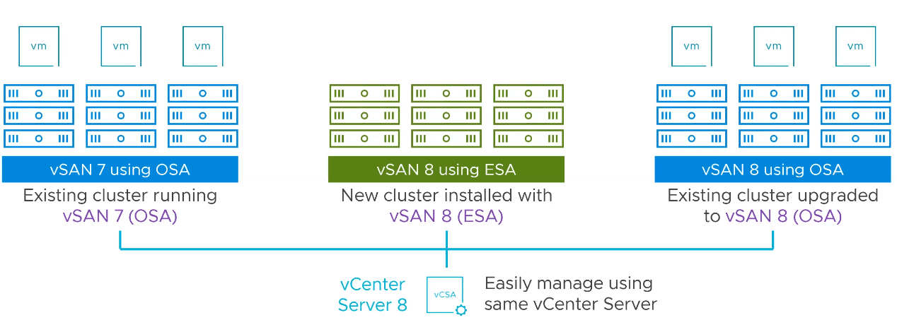
Putting it in a nutshell: The vSAN ESA architecture is an optional data storage architecture. The traditional disk group model will continue to exist – even under vSAN 8.
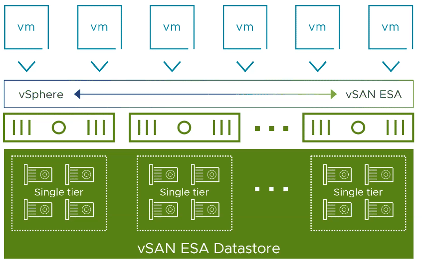
VMware vSAN ESA is a flexible single-tier architecture. This means that it does not require disk groups and no longer distinguishes between cache and capacity layers. It is optimized for the use of modern NVMe flash storage. All storage devices of a host are gathered in a storage pool.
There is no upgrade path from the diskgroup model to ESA. Thus, the new architecture can only be used in greenfield deployments. The vSAN nodes must be explicitly qualified for this. There will be dedicated vSAN ReadyNodes for ESA.
Now what can vSAN ESA offer?
- More efficient high performance data storage. The use of space-saving storage methods such as Erasure-Coding RAID5/6 is no longer associated with the current performance penalties. RAID6 with the performance of RAID1.
- Snapshots with significantly less impact on performance.
- Adaptive erasure coding. If the number of nodes is lower, an EC storage policy can still be used. vSAN 8 dynamically adjusts the number of minimum required fault domains to the number of nodes.
Prerequisites
How can users adopt the new vSAN8 ESA?
- Certified hardware: ReadyNodes approved for ESA are required. The VMware HCL will be extended for ESA, so that in future it will also be possible to build your own hosts if all components are approved for ESA. This will of course be fewer than with the normal vSAN HCL.
- VMware vSAN ESA requires Advanced or Enterprise licenses.
- VMs need to be migrated to a greenfield cluster. There will be no upgrade path from traditional Original Storage Architecture (OSA) to ESA.
- ESA and OSA clusters can coexist in the same vCenter.
Under the hood
The new vSAN ESA essentially uses two new additional layers on the existing vSAN storage stack.
Log-Structured File System (LFS)
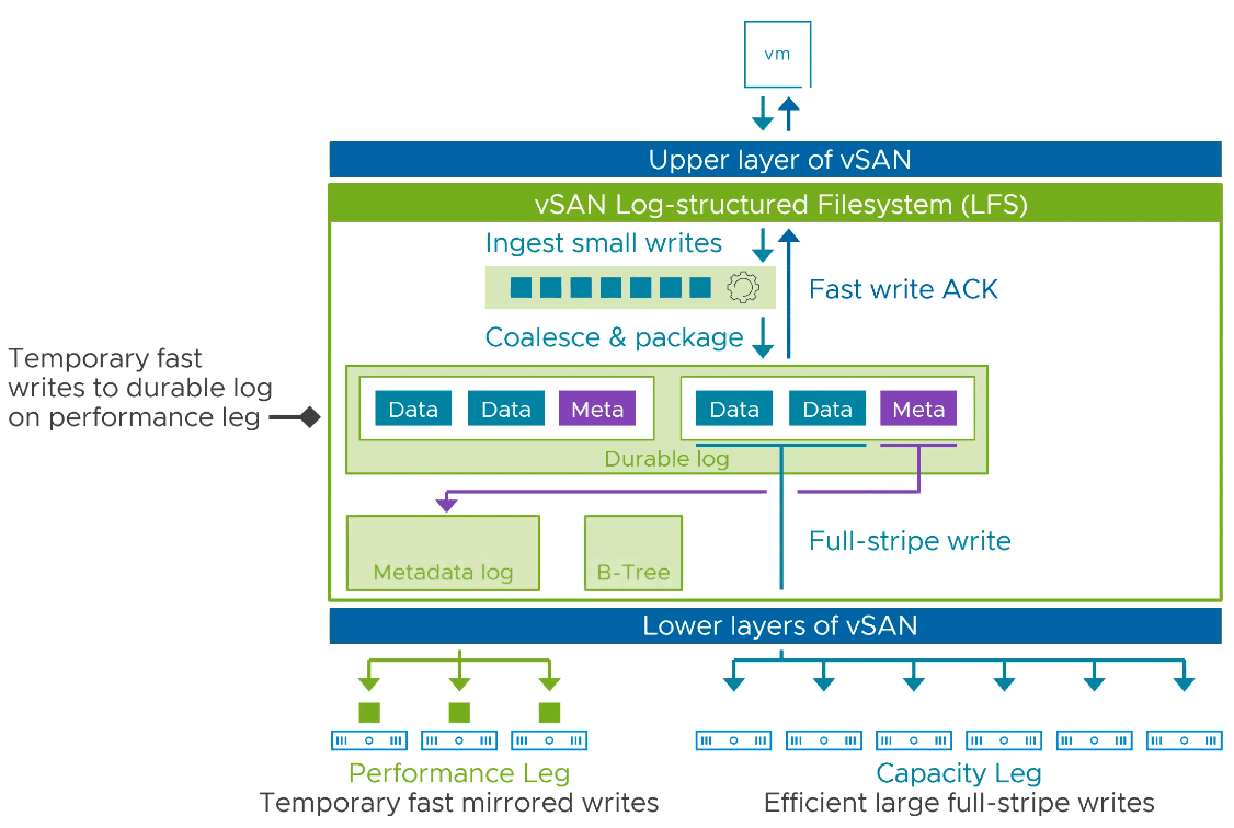
vSAN ESA uses a new log-structured file system (LFS) that is highly optimized for large I/O processing. Incoming data can be stored very quickly and in a space-efficient manner. It allows high-performance snapshots and reduces I/O amplification in the data path.
As data storage size increases, it has not been the processing of the data that has been problematic, but the processing of the metadata. Both data and metadata are written to the Durable log first and can return a Write-ACK immediately.
Log-Structured Object Manager
The new Log-Structured Object Manager delivers the data to the storage devices as quickly as possible, so that the native speed of the flash device becomes the limiting factor and not the data path.
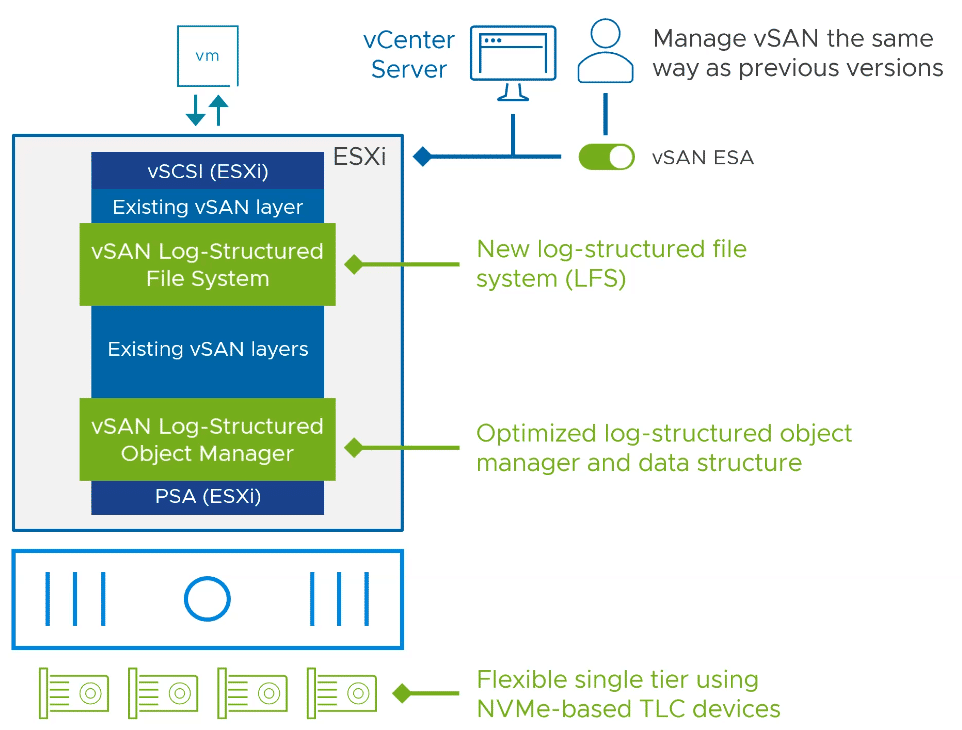
The combination of the two new layers enables a single-tier architecture in which it will no longer be necessary to distinguish between cache and capacity devices.
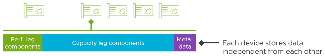
LFS has what is known as a performance leg and a capacity leg. However, these are not different flash device classes. All devices are in the same pool. When managing new devices, there is a Storage Pool Clain and no disk groups.
First, data is received and temporarily stored in the Durable Log (Performance Leg). From there, the data is moved to the capacity area, while the metadata is reorganized and stored very efficiently in the metadata log.
Storage Policy and Component-Placement
Although a lot has changed at the filesystem level, little has changed for the admin. Objects are still divided into components and distributed across different hosts. What is new are the performance leg components, which are also distributed across multiple hosts. The graphic below shows three different storage policies and the resulting distribution of components.
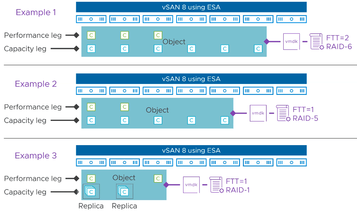
The capacity leg largely corresponds to the original component distribution in the previous OSA architecture. What is new are the components of the performance leg, which are always stored as RAID-1 mirrors. The number depends on the FTT of the applied policy. Performance Leg components may be located on the same host as the corresponding Capacity Leg components.
Higher Efficiency in Data Processing
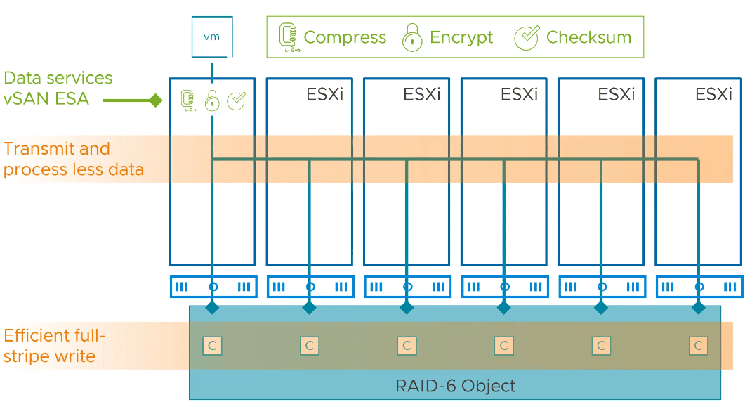
To highlight one of the advantages of ESA over traditional OSA, let’s take an example of a VM object with a RAID-6 EC policy that also applies data services such as compression and encryption. All these data services take place on each participating host at the disk group level.
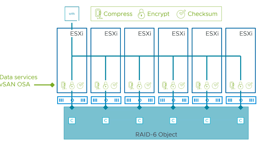
VMware vSAN ESA shifts the processing of these data services to a single host at the entrance of the stack. Compression, encryption and checksum calculation takes place at the host that received the data. As a result, the data is processed once and there is no I/O amplification. The processed data is then distributed over the required number of hosts.
Adaptive RAID-5
A new adaptive RAID-5 erasure coding adapts to cluster sizes. Under normal circumstances with 6 or more hosts, a 4+1 model with 125% storage requirement is applied. That is, four data compoents and one parity compoent. This requires one more host than RAID-5 in earlier vSAN clusters that used a 3+1 model. For smaller clusters with 3-5 hosts, the EC adapts RAID-5 and runs a 2+1 model with 150% storage requirements. In all cases, an attempt is made to keep one host as a spare. Therefore, the 4+1 model is only used for clusters with 6 hosts or more. Before a 4+1 RAID-5 is transferred to a 2+1 model – or vice versa – the cluster waits 24 hours. This prevents maintenance work or host failures from triggering relocation processes prematurely.
Adaptive RAID-5 allows the use of an EC policy even in smaller environments.
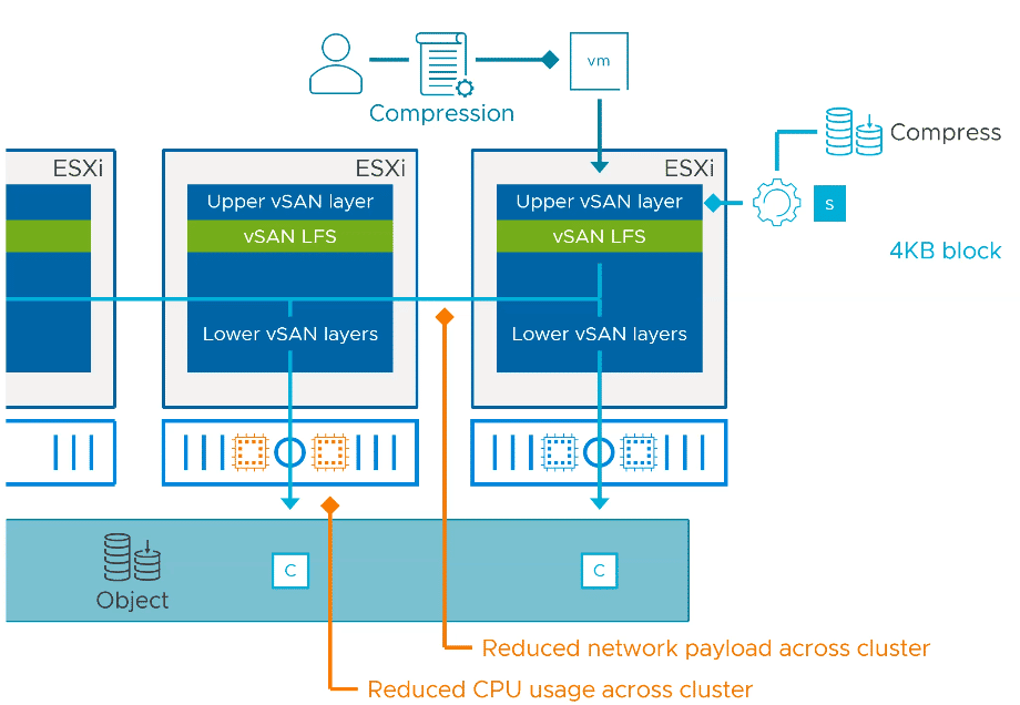
Storage Policy-based Compression
Under ESA, compression is no longer a cluster property, but can be set per object using a policy thanks to the new file system. With ESA, it is no longer necessary to perform a rolling reformat of the datastore in order to use compression.
Compression is enabled by default. The CPU overhead is minimal.
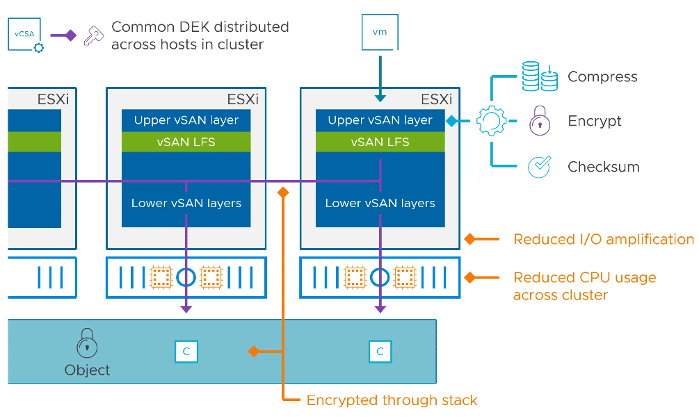
Talking about Encyption
Conventional vSAN clusters had Data-at-Rest-Encyption and Data-in-Transit-Encyption. Under ESA, this distinction no longer exists. Similar to compression, encryption occurs high up in the storage stack. This eliminates the need for multiple encryption and decryption operations when writing to the storage device.
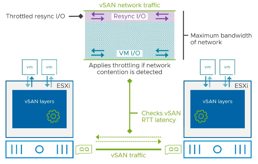
Intelligent vSAN Traffic Shaping
Resync traffic on the vSAN network can be throttled to avoid adversely affecting operational VM I/O traffic. Throttling can be tuned on a per-host basis.
New High Performance Snapshot Engine
The snapshot engine has been completely reworked and optimized for high performance. The consolidation of snapshots has been improved by up to a factor of 100 compared to OSA. Under ESA, even snapshots of objects in the “degraded” state are possible.
Integration with third-party VADP solutions can be seamlessly achieved. This also means higher performance for SRM and vSphere replication.
The user interface now displays clearly the memory consumption of a snapshot.
600 GB Cache Limit
One change will especially delight users of the classic OSA architecture. So far, the maximum usable capacity of a cache device was 600 GB. All areas beyond that were used as a wear-out spare. With vSAN 8, the limit has now been raised to 1.6 TB per disk group. A larger write cache means reduced I/O load on the capacity tier.
Links
- VMware – Announcing vSAN 8
- VMware Blog – An Introduction to the vSAN Express Storage Architecture