Network topology 101 for Virtual Infrastructures
I usually don’t like writing about obvious matters. Yes, fire is hot – night is dark and ice is cold. But in recent times I’ve witnessed some network topology designs (?), that made me frown.
I admit, that in some cases the situation is based on a lack of budget or just structures that have grown over years. I can understand that and it’s no shame. It’s my job to give advices and help to re-design.

On the other hand there are environments who boast with high class components that have cost a fortune and which are organized in such an inefficient way that it almost hurts.
This article is not intended as a networking deep-dive. It’s a shallow 101 about network design that should be common knowledge. It’s a guide for the novice but I’d be happy to get responses by experts too.
The Basics
First let’s start with four simple networking requirements for Virtual Infrastructures.
- redundancy
- resiliency
- bandwidth
- latency
Redundancy
Network connections between ESX servers are extremely important. and they are even more important between vSAN nodes. You should avoid to have any single-point-of-failure (SPOF). That means, if you loose one component, there should be at least one spare to keep the connection alive. Therefore your vSwitches should have more than one physical uplink. These uplinks connect to more than one physical switch, which are powered by more than one independent source of power. These switch boxes should have more than one link or path to each other. If somebody accidentally cuts one path there will still be another one to maintain the connection.
Resiliency
Once you’ve accomplished redundancy you might face your next obstacle.
Say hello to spanning tree.
The Spanning-Tree-Protocol (STP) is a very useful protection mechanism against network loops. If you build a network loop, STP will shut down all but one paths to destination. To maintain this protection there have to be negotiations and elections of the root bridge between all switch components within the network. This takes some time, ranging from milliseconds to many seconds, depending on the STP protocol and the size of the network. STP negotiantions are poison for your ESX hosts, because during that time the network will be down for communication. Every time the topology changes there will be a new negotiation with nasty side effects to your virtual infrastructure. Host get isolated from the cluster, HA might kick in, healthy VMs might get restarted on other hosts. No fun! I will show an alternate approach to the subject later to avoid that problem.
Bandwidth
Bandwidth is one of the first parameters customers usually mention. Of course more is better. But you have to think twice unless you want to waste a lot of money. Having a 10 Gbit/s backbone today is state of the art and should be enough for most infrastructures. If you want to go for 40 Gbit/s or even more, you should carefully watch the usage of your current backbone. Most likely you won’t be able to saturate 10 GBit. Keep in mind that a single QSFP+ (40 Gbit/s) costs more than four SFP+ (10 Gbit/s).
Latency
When talking about latency we usually refer to round-trip latency, or round-trip-time (RTT). That is the time between sending a packet and receiving the answer. Not taking into account the processing time for the packet on the destination side. Best example is a network PING. In shortrange LAN environments and with recent hardware, latency usually isn’t a problem.
Let’s focus on the first two topics Redundancy and Resiliency, which are the most important ones for a stable virtual environment.
Have a spare for everything.
This is one of the basic concepts in virtualization: No single point of failure. Whatever might fail, you should have a spare component that kicks in. It starts with the ESXi hosts themselves. The reason why we build clusters, is to allow at least one host failure within the cluster. That is neccessary because in a common x86 architecture server there are many single-points-of-failure. For example a mainboard or a SAS-controller. So the whole chassis has to be made redundant in some way, which can be achieved by an ESX-Cluster.
With storage it is a litte different. Storage units usually have every part doubled. Two controllers, with multiple connection modules for FibreChannel or iSCSI. Disks are organized to RAID-sets in order to tolerate one or more disk failures.
Network-Switches and FC-Fabric devices are single points of failures too. That’s the reason why we need to double them and provide alternate paths to targets.
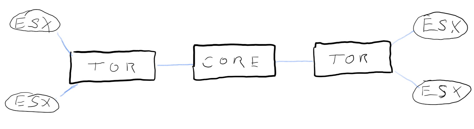
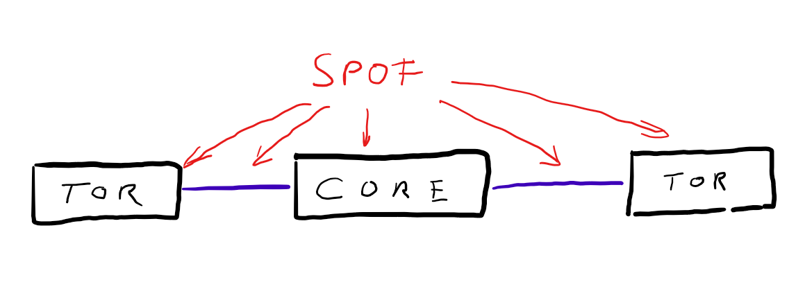
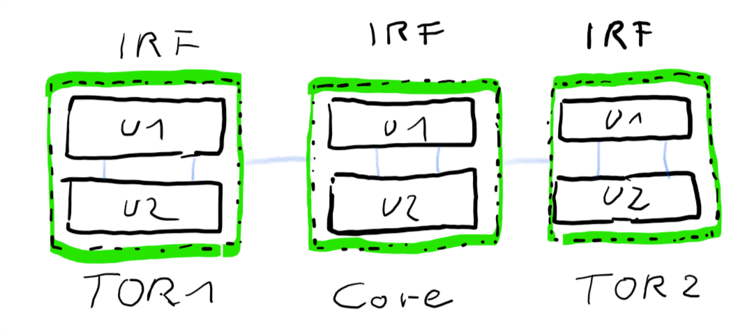
Let’s start with a simple network topology. We have Top-of-Rack (TOR) switches to connect hardware within a rack or cabinet. And we have a core-switch in the center that interconnects all the TOR switches. This is a simple star-shaped network.
[+} resilient, no loops
[-] no redundancy
Redundancy is a key requirement and this architecture has none. It contains many Single-Points-of-Failure (SPOF). Single switch-units and single links. If any of them is going to fail, the whole connection wil break down.
Let’s add some redundancy by doubling every switch. I.e. double core-switch, double TOR-switches etc.
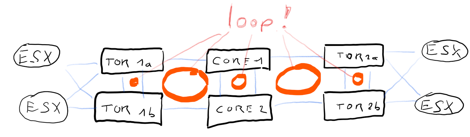
[+] fully redundant
[+] no SPOF
[-] many loops, requires spanning-tree protocol
Now we’ve eliminated all SPOFs, but at the same time we’ve created many loops in our network. Thanks to spanning tree protocol (STP) this is a legitemate design, but every change in the topology will cause STP negotiations. Trust me, your ESX infrastructure will not like it! One flipping link can nuke a whole ESX-Cluster. If you want to learn some funny things about HA, split brain scenarios, and desaster recovery, try this design and have a nice day. 🙂
At this point it seems that we’re caught between a rock and a hard place and have to choose between redundancy and resiliency. I’ll show you in the next section that you can have the best of both worlds without the negative aspects of each construct.
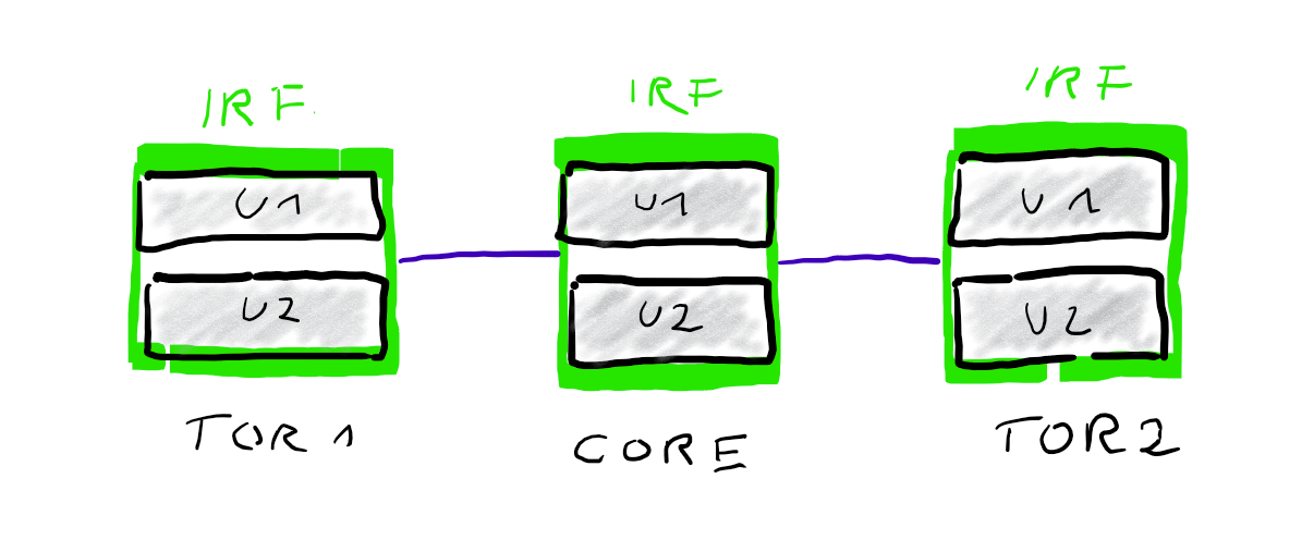
Switch redundancy
Many switch vendors offer techniques to cluster multiple devices to a single logical unit. HPE for example offers Intelligent-Resilient-Framework (IRF) and Cisco offers Virtual Switching System (VSS). Both concepts are very similar. Physical units are connected by IRF-links (HPE) or VSL (Cisco).
Once connected they act as one logical unit, sharing a common configuration. One unit is master, all others are sla… subordinates. 😉 Some time ago I’ve published an article on how to build and configure an IRF cluster.
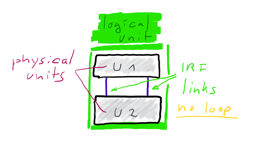
Bundling two ore more physical switch-units to one logical unit, greatly simplifies your logical architecture.
Link redundancy
Now that we’ve clustered the switch units, it’s time to “cluster” the links between switches. If we use more than one physical link between our (clustered) switch-units, STP will block one of them and we will see STP negotioations. But we can form aggregates of multiple links to form one logical link. These aggregates are known as Etherchannel (Cisco) or Trunks (HPE), but the protocol link-aggregation-protocol (LACP) is the same and defined in IEEE 801.1AX .
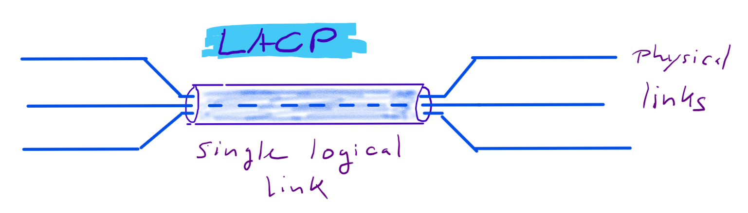
From a physical point of view a redundant connection between TOR switch and core switch looks like this.
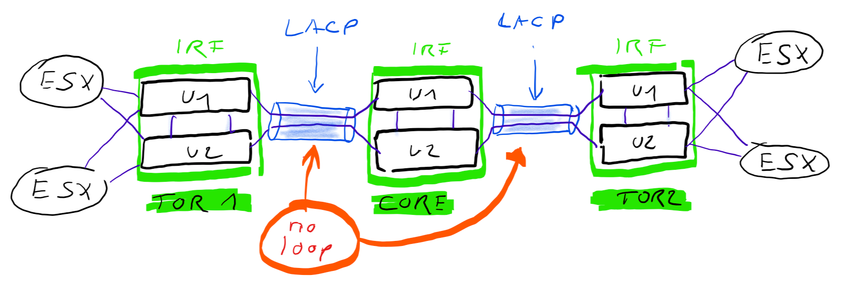
From a logical point of view it looks like this.
While IRF / VSL technology is used to cluster multiple physical switch-units to one logical unit, so do link-aggregations bundle multiple physical links to one logical link. From a Spanning-Tree point of view these are single links and there is no need to block anything. From a physical point of view you have full redundancy. If you loose one physical link for example your logical link remains intact. Only your overall bandwitdh will be reduced by the bandwidth of your lost link.
LACP will utilize your physical links in a round-robin manner. For example, if you bundle two 10 Gbit links into a link aggregation. This logical link will have 10+10 GBit/s. The burst rate of a single data connection will be still 10G (not 20G). But you can have two connections with 10G burst at the same time. Under normal conditions your throughput will be roughly doubled.
What about vSwitches?
There’s no need to be concerend about loops between vSwitches and physical switches. ESXi vSwitches only forward frames from either VM to VM or from VM to an uplink-NIC. A vSwitch is not running spanning tree protocol and will therefore not send STP Bridge Protocol Data Units (BPDU). Incoming BPDU frames from physical switches will be discarded by the vSwitch. That’s the reason why we can have multiple uplinks from one vSwitch to one physical switch, without getting uplink ports blocked by STP. As a rule of thumb: set the switchports with your ESX-NICs into Edge-Mode. I.E. they will not take part in STP negotiations at all and will not trigger topology changes.