
Automatic VLAN assignment and use of DHCP relays
Software defined datacenters (SDDC) enable us to keep many components within the hypervisors software layer. But sooner or later we need to exit that layer in order to get in touch with the user. Usually Thin- or Zeroclients are used as VDI endpoints. Those hardware boxes are connected by LAN and need to have an IP address.
I will demonstrate how to assign endpoints to separate them into subnet segments and VLANs and still assign IP addresses by a centralized DHCP server.
Requirements
- Dedicated VLAN for VDI endpoints
- Dedicated subnet for VDI endpoints
- No client configuration. Endpoint needs to work out of the box.
- Foolproof switch placement. Device needs to work on any switch ‘port.
Constraints
- Company’s centralized DHCP server has to manage leases. No dedicated DHCP server in VLAN.
- Estimated number of endpoints >256
Environment
- Class B intranet 10.1.0.0/16
- HPE Switch infrastructure with 5700 Series as Core and 5130 series as access switches
- Private cloud based on vSphere 6.0
Planning
Clients will get a dedicated class B subnet, because expected number will be greater than 255. This subnet will be in a dedicated VLAN. DHCP discover packets can’t traverse routers and reach the central DHCP server. Therefore we need to utilize a DHCP relay on the core switch.
VLAN and Subnet
First we need to define a VLAN on all switches involved. That’s the access switches and the core switch.
system-view
vlan 2
VLAN 2 is created.
Next we need to allow VLAN 2 on all link aggregation interfaces between switches. That has to be done on each side of the trunk.
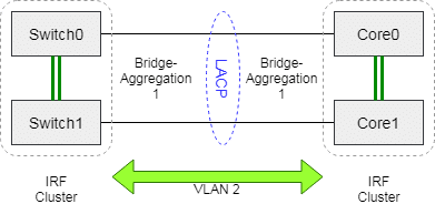
Imagine there’s a link aggregation 1 from core switch to access switch 1 and link aggregation 2 from core to access switch 2. Then we have to excecute these commands on the core switch.
system-view
interface bridge-aggregation 1
port trunk permit vlan 2
quit
interface bridge-aggregation 2
port trunk permit vlan 2
quit
quit
Now VLAN 2 is permitted on both link aggregation interfaces leading to access switch 1 and 2. We also have to grant VLAN 2 from the opposite direction on access switch 1 and access switch 2. On both access switches the link aggregation interface has number 1. These are the commands to permit VLAN 2 from an access switch to the core. They have to be issued on both access switch 1 and access switch 2.
system-view
interface bridge-aggregation 1
port trunk permit vlan 2
quit
quit
Now we can handle packets in VLAN 2 on access switches 1 and 2 and the core.
In addition we need a VLAN interface on the core switch as a gateway.
system-view
interface vlan-interface 2
ip address 10.2.0.1 255.255.0.0
description VDI endpoints
name VDI endpoints
quit
quit
We now have a VLAN interface in VLAN 2 with IP address 10.2.0.1. That is the gateway address for all clients in VLAN 2. Creating a VLAN interface automatically creates a route. Clients in subnet 10.2.0.0 can now communicate with clients in subnet 10.1.0.0.
DHCP Relay
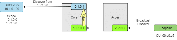
A client in subnet 10.2.0.0 can’t reach a DHCP server in subnet 10.1.0.0 directly. To make it possible we need a DHCP relay on the core switch. It relays DHCP communication on behalf of the client.
We only need a relay on the core switch. IP address of our DHCP server in the example is 10.1.0.100.
system-view
dhcp enable
interface vlan-interface 2
dhcp select relay
dhcp relay server-address 10.1.0.100
quit
quit
Configure DHCP server
To become responsible for subnet 10.2.0.0, our DHCP needs another scope. It can then offer leases for requests coming from the 10.2.0.0 range. All others will get addresses from the default range.
Automatic VLAN assignment
You can assign devices to different VLANs according to their hardware properties. An IP phone will get a different VLAN assigned than a printer or a VDI endpoint. This should happen on the switch port without further configuration on the device. Doing so will reduce administrative errors.
A common property of all VDI endpoints (from the same vendor) are their first 24 bits of their MAC addresses. These 24 bits are called Organizationally Unique Identifier (OUI). In our example all endpoint have an OUI like 00:e0:c5 (=BCOM electronics Inc.). All endpoint devices will only get connected via access switches. Therefore we only have to configure access switches. In our example it’s a 48-port switch model. That’s why we configure ports 1/0/1 to 1/0/48.
system-view
mac-vlan mac-address 00e0-c500-0000 mask ffff-ff00-0000 vlan 2
interface range gigabitethernet 1/0/1 to gigabitethernet 1/0/48
port link-type hybrid
port hybrid vlan 2 untagged
mac-vlan enable
vlan precedence mac-vlan
Once a packet with MAC address 00:e0:c5:xx:xx:xx reaches a configured switch port, it will automatically assigned to VLAN 2. There’s no need to configure the endpoint device.
If you’re using an IRF-cluster you nee to adjust the line with the interface range accordingly. Here’s an example for an IRF-cluster consisting of 3 units:
interface range gigabitethernet 1/0/1 to gigabitethernet 1/0/48 gigabitethernet 2/0/1 to gigabitethernet 2/0/48 gigabitethernet 3/0/1 to gigabitethernet 3/0/48