If you’ve missed it read part 1 – Planning phase.
Unboxing
Last Tuesday a delivery notification made me happy. Hardware shipping is on its way. Now it was time to get the cabling ready. I can’t stand Gordian knots of power cords and patch cables. I like to keep them properly tied together by velcro tape. To keep things simple, I’ve started with a non-redundant approach for vSAN traffic and LAN. Still eight patch cables that had to be labeled and bundled. Plus 4 cables for the iPMI interface. I found out later that the iPMI interface will make a fallback to the LAN interface if not connected. That’s nice. Saves me four cables and switch ports.
Host Hardware
All four hosts came ready assembled and had accomplished a burn in test. The servers are compact and have the size of a small pizza box. They’re 25,5 cm wide, 22,5 cm deep and 4,5 cm high. But before I’m going to press power-on, I need to have a look under the hood. 🙂
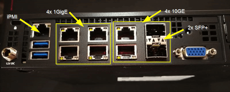
Let’s start with the rear side. As you can see in the picture, there are plenty of interfaces for such a small system. In the lower left corner there’s the 12V connector which can be fastened by a screwcap. Then there are two USB 3.0 connectors and the iPMI interface above them. The iPMI comes with console and video redirection (HTML5 or Java). No extra license needed.
Then we have 4x 1 Gbit (i350) ports and four 10 Gbit (X722) ports. Two of which are SFP+. In the lower right there’s a VGA interface. Thanks to console redirection this is not necessary. But it is good to have one in emergencies.
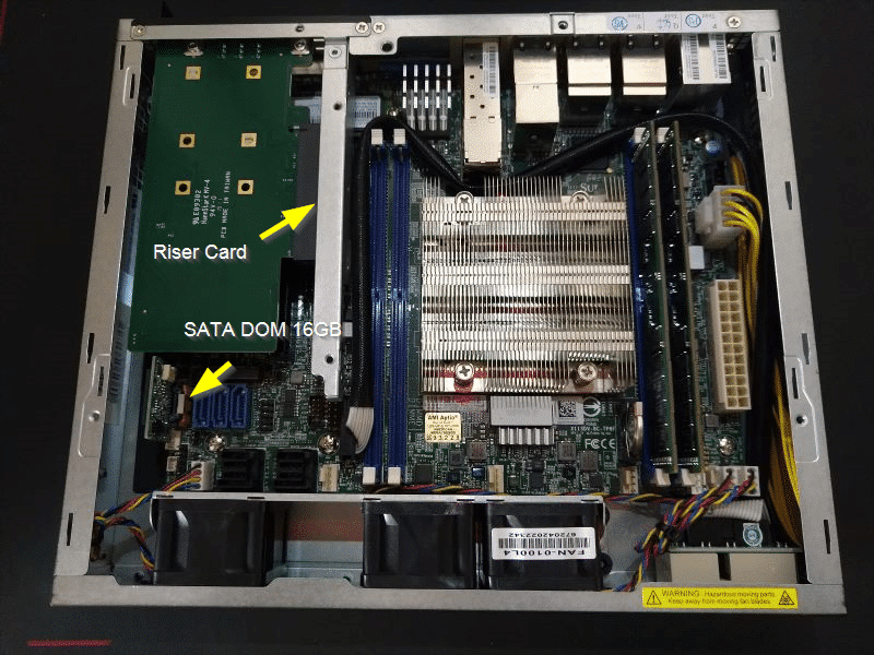
Inside the case
Taking of the top of the case, there’s still a metal shield (not shown here) that can be easily unscrewed. Rear side is on top of the picture with all its network connectors. In the middle there’s the CPU with four memory slots. On the bottom part we see a row of fans which turned out to be quite silent after booting. In general my Netgear switch is louder than the four units together.
Left of the middle you can see the PCIe riser card. The mainboard has only one M.2 slot for a flash device. So I had to add an M.2 PCIe host bus adapter to get two more M.2 connectors. It doesn’t fit directly onto the PCIe slot, so I had to use a PCIe riser card. We see the M.2 HBA from below on the left of the riser card.
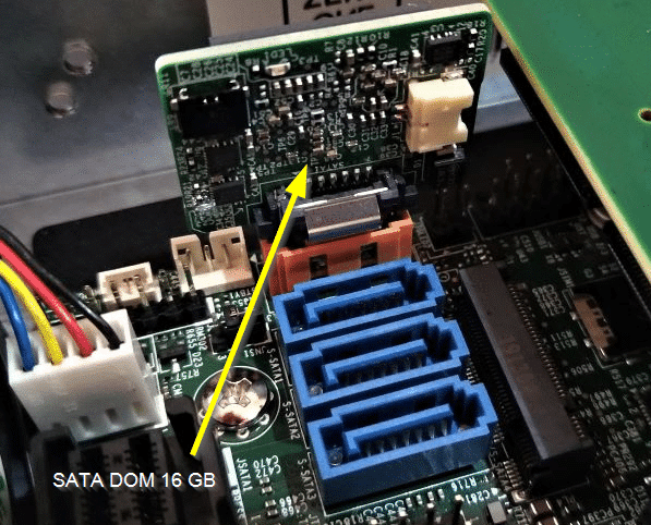
SATA DOM
To install ESXi we need a small boot medium. Supermicro offers a small 16 GB disk-on-module (DOM) which is directly plugged into a SATA connector.
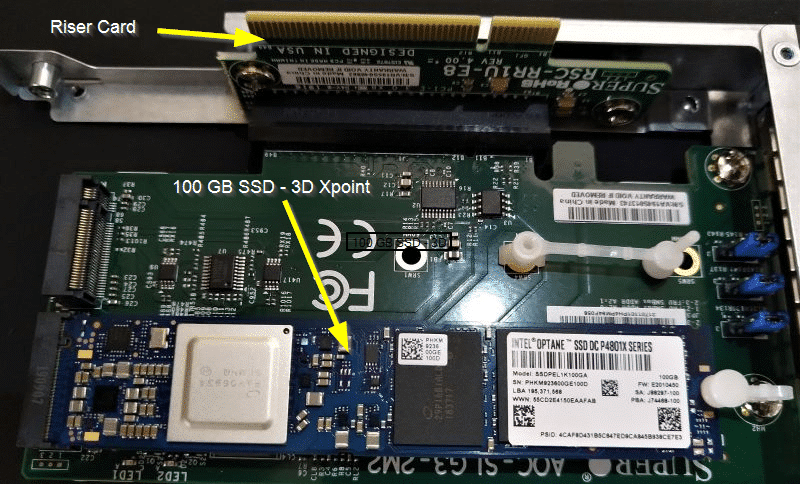
Riser Card and HBA
On the next picture we see the PCIe riser card (taken out of the server) with the M.2 dual host bus adapter card. One Intel Optane card is already connected to one of the two slots.
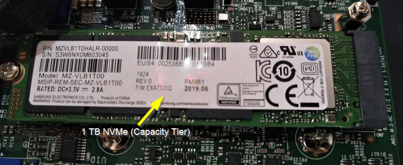
Next we see the mainboard with its single M.2 connector, which is used for the capacity tier. Samsung SSD is already installed.
You may ask now, why we didn’t put the Samsung SSD onto the dual slot HBA and the Optane onto the mainboard. We cannot mix devices on the HBA and we can only have one cache device per disk group. In this configuration we won’t be able to scale up capacity by adding a second cap-tier SSD. The answer is very simple. The Optane card doesn’t fit onto the mainboard. So I had to bite the bullet and leave one M.2 slot unused.
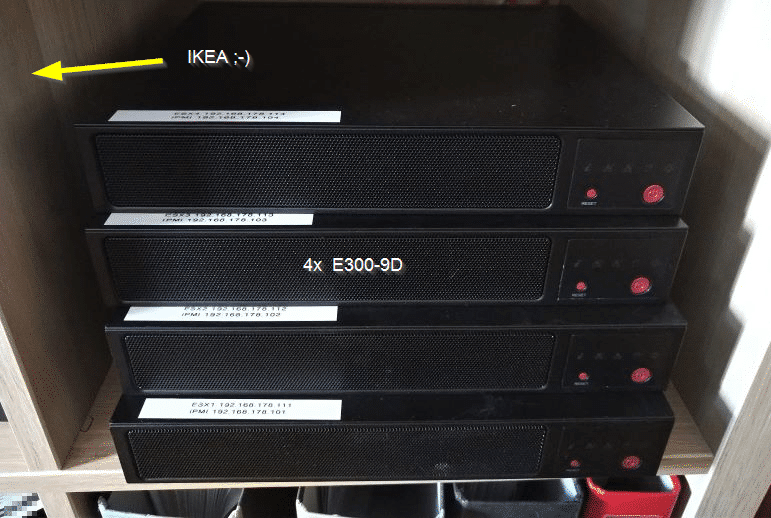
Micro Rack – designed in Sweden
All four units fit well into a low budget IKEA rack. Plugging and unplugging patch cables is a bit of a pain, but it works.